
Consulting phone
022-83711102
0311-67163596
022-83711102
Mechanical part of 1 electric upsetting machine
1.1 body and attachments
The body is made up of 5 parts, namely, the front panel, the upper and lower supporting boards, the rack and the cover plate. The body is equipped for heating transformers and two conductors.
1.2 safety protection device
The safety protection device is made up of two transparent protective doors, door suction and induction switches. When the safety door is opened, the current upsetting machine will immediately stop working to protect the safety of the person.
1.3 clamp and automatic middle device
The clamp and the automatic middle device are composed of a pair of clamps, a pair of jaw jigs, a tightening cylinder and a starting proportional valve. The tightening cylinder simultaneously pulls the two clamps between the left and the right and the workpiece is clamped by each other.
1.4 anvil back and back device
The anvil return device is composed of a servomotor, a precision planetary reducer, a set of ball screws, a sliding slide block and a set of anvil head pulling devices. The servo motor power is driven by the planetary reducer to rotate the ball screw so that the slider moves up and down.
1.5 hydraulic forging device
The hydraulic upsetting device is composed of a set of independent hydraulic stations, a uniform heavy oil cylinder and a movable slide block. The independent hydraulic station directly drives the heavy oil cylinder, and the oil cylinder drives the movable slide block to move up and down.
1.6 bending device for workpiece
The workpiece anti bending device is composed of two adjustable cylinders and a pair of clamps. The two cylinders directly drive two clamps to the right position to prevent the valve from bending.
1.7 cooling water system
The cooling water system is composed of three waterways. The first road cooling water goes through the inlet water distributor through the inlet water separator and out through the heating transformer to the water separator. The other two roads are connected to the two sides of the clamp respectively. All the systems are made of stainless steel (to prevent rusting and clogging).
1.8 pneumatic device and piping system:
This equipment is equipped with proportional pressure valves, solenoid valves, filters and piping systems required for electric upsetting. The pressure of the gas source should not be less than 4.5kgf/cm.
2 electrical parts
2.1 electric control system
Electrical control system circuit diagram (see chart), mainly include: programmable controller, output amplification isolation plate, proportional valve, proportional amplification board, heating controller, thyristor, heating transformer and some protection components. The electrical control cabinet is installed for maintenance and maintenance independently.
2.2 electric upsetting and heating system
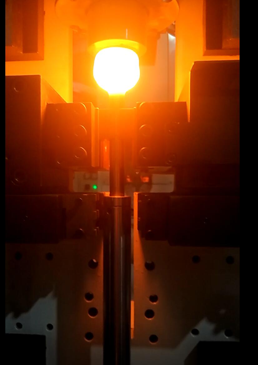
The electric upsetting heating system is located in the body of the electric upsetting machine, which is composed of a heating transformer, an output copper connection, an upper electrode copper plate and a clamp copper electrode. The upper electrode and the clamp electrode are respectively connected with two electrodes of the transformer, and the workpiece is heated by a large current in two electrodes.
2.3 monitoring system
The monitoring system of electric upsetting machine is based on real-time monitoring of cooling water flow velocity, real-time monitoring of the electrode temperature on the anvil, real-time monitoring of oil temperature in hydraulic system, real-time monitoring of workpiece temperature and real-time monitoring of system air pressure. The omnidirectional monitoring method keeps the electric upsetting machine running in normal working condition to prevent the machine tool from causing illness and reduce the reject rate.
2.4 button box
The button box is made up of a button and a control panel. The button is convenient for the operator to debug and run the machine tool. The control panel can check the current operation of the machine tool, such as the working temperature of the workpiece, the stock temperature, the hydraulic oil temperature, the flow rate of cooling water, the fault code and the processing parameters.
022-83711102
0311-67163596
Contact usCONTACT US
022-83711102 / 0311-67163596
fax: 022-83711102
Tianjin City
phkj2008@hotmail.com

Pay attention to us
© 版权所有 2017 sjzdydz.com All Rights Reserved 津ICP备17009726号
Technical support:Emperor Yi planning
© 版权所有 2017 sjzdydz.com All Rights Reserved
津ICP备17009726号 技术支持:帝易企划